


Dim Bulb Tester tool current limiter for antique radios, amplifiers and vintage electronics.
Regular price
$74.99
Retro Radio Shop Dim Bulb Tester
The Dim Bulb Tester (DBT) - an essential safety tool for the initial power-up of vintage radios, amplifiers, and other restored electronics.
1. Firstly, what Is a Dim Bulb Tester?
To start, a Dim Bulb Tester is a simple series circuit consisting of a standard Incandescent Bulb wired in series between the AC mains and the Device Under Test (DUT). The bulb acts as a current-limiting resistor - if something is wrong inside the equipment, consequently, the bulb glows brightly and absorbs the fault energy instead of letting it destroy the power transformer or other components, for instance.
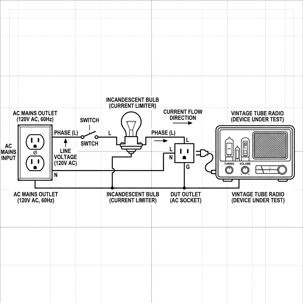
Series circuit - the bulb sits between the mains and the DUT, limiting the maximum current that can flow regardless of what happens inside the equipment
2. Secondly, How the Dim Bulb Tester Works - Theory
The Dim Bulb Tester (DBT) operates on the principle of a Series Circuit . Because the bulb and the DUT are in series, they share the same current - and the total voltage divides between them according to their relative resistances.
Voltage Division
The mains voltage splits across the bulb and the DUT. If the DUT is healthy and drawing normal current, most of the voltage appears across the DUT and the bulb barely glows. If the DUT has a fault drawing excess current, the bulb claims more of the voltage and glows brighter - critically, warning you before damage occurs.
Current Limitation
Even in the worst case - a dead short inside the DUT - the maximum current that can flow is set by the resistance of the bulb filament. A 60 W bulb at 120 V has a hot resistance of around 240 Ω, limiting fault current to roughly 0.5 A. For instance, without the DBT, the same short would draw many amperes, burning out windings and components instantly.
Positive Temperature Coefficient - The "Soft Start" Effect
A Tungsten Filament has non-linear resistance: as current heats the filament, resistance rises. Therefore, the milliseconds after switch-on, the bulb's resistance is very low, allowing normal inrush current for charging capacitors and heating tube filaments. As the filament heats, resistance increases and the circuit settles into its steady-state limiting behaviour. As a bonus, this "soft start" is beneficial for electrolytic capacitors being reformed after years of storage.
Why Not a Resistor?
Similary, a fixed resistor also limits current, but unlike a bulb it gives no visual feedback, dissipates power as heat even when the DUT is healthy, and, importantly, cannot provide the self-regulating soft-start behaviour of a tungsten filament. Given this, the bulb's glow is your real-time indicator of the circuit's health.
3. Thirdly, Dim Bulb Tester Bulb Selection and Wattage
Importantly, the effectiveness of the tester depends entirely on choosing the correct bulb wattage for the equipment being tested. The right bulb allows normal operation to proceed at a slightly reduced voltage while still glowing brightly enough to flag a fault.
As a general rule, select a bulb with a wattage rating approximately 1.5 to 2 times the expected power draw of the DUT. Importantly, a bulb that is too low in wattage will limit the DUT's voltage so severely that it cannot power up correctly. Conversely, a bulb that is too high will glow so dimly on a real fault that you might miss the warning.
Moreover, one of the most useful features of a well-designed Dim Bulb Tester (DBT) is the ability to swap bulbs easily using a standard lamp socket. For example, keeping a selection of bulbs on the bench - 25 W, 40 W, 60 W, 100 W, and 150 W - lets you tune the tester to any equipment you encounter.
| Device Under Test | Approx. DUT Power | Recommended Bulb |
|---|---|---|
| Typical 5-tube table radio | ~30 - 40 W | 40 - 60 W |
| Large console radio | ~60 - 80 W | 75 - 100 W |
| Guitar amplifier (small) | ~40 - 60 W | 60 - 75 W |
| Guitar amplifier (large) | ~80 - 120 W | 100 - 150 W |
| Hi-fi amplifier / console | ~100 - 150 W | 150 - 200 W |
Start Low, Then Step Up
If you are unsure of the DUT's power consumption, start with a lower-wattage bulb (e.g. 40 W). If the radio subsequently appears to power up correctly but sounds weak or the voltages are low, step up to the next bulb size, The conservative approach, detailed above, gives old capacitors more time to reform gradually.
4. Operating Procedure
- Firstly, ensure the power switch on the Device Under Test (DUT) is in the OFF position before connecting anything.
- Install the appropriate wattage incandescent or halogen bulb into the tester's socket.
- Plug the DUT into the outlet on the tester. Do not power on the DUT yet.
- Plug the tester into the AC wall outlet (or isolation transformer if required).
- Switch the DUT to its ON position and observe the bulb closely. The bulb's initial flash and steady-state brightness tells you the electrical health of the DUT immediately.
- After a stable, dim glow is confirmed, allow 2 - 3 minutes for electrolytic capacitors to reform before proceeding with voltage measurements.
5. Subsequently, Interpreting the Bulb's Behaviour
The visual behaviour of the bulb is your primary diagnostic instrument when using a Dim Bulb Tester. Therefore, learn to read these three scenarios:
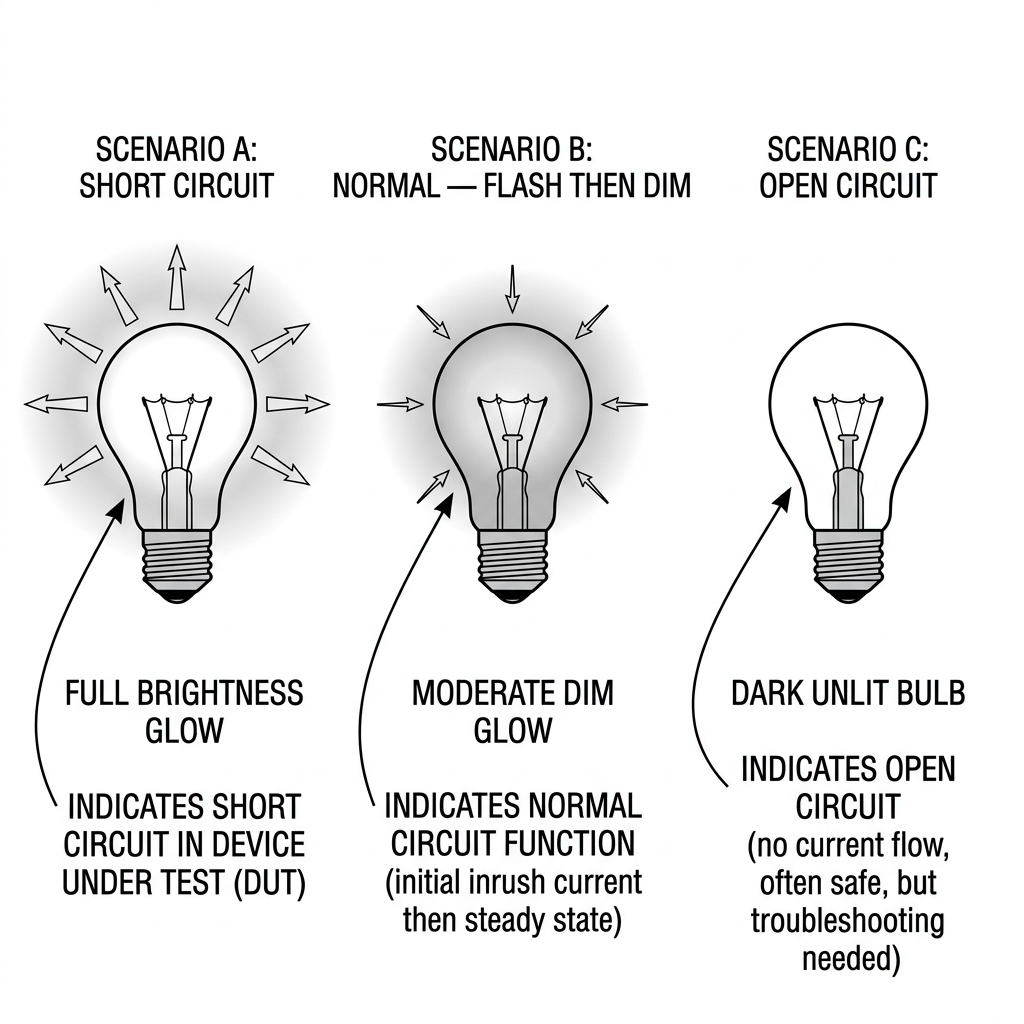
Bulb behaviour at a glance - bright constant = short; flash then dim = normal; no glow = open circuit
Bright Glow - Constant
Indication: A short circuit exists within the DUT. The bulb is dropping nearly the full mains voltage, correctly protecting the DUT, as designed, from destructive fault current.
Action: Power off immediately. Investigate the power supply section - filter capacitors, rectifier tubes or diodes, and the power transformer primary winding are the most likely culprits.
Bright Flash, then Dim Glow
Indication: Normal behaviour. The initial flash is inrush current charging filter capacitors and heating tube filaments. As the DUT stabilises, current drops and the bulb dims, as a result. Note the DUT is operating at slightly reduced voltage - this is expected and safe.
Action: Proceed with voltage measurements on the DUT. Once stable, unplug from the DBT and connect the DUT directly to the mains for final full-voltage verification.
No Glow at All
Indication: An open circuit exists - no current is flowing through the DUT. The problem is upstream of the main power supply.
Action: Check for blown fuses inside the DUT, a broken or unplugged power cord, or a failed power switch. Verify the tester itself is working by briefly plugging in a known-good lamp.
6. Lastly, Final Dim Bulb Tester Verification
In conclusion, once the DUT is confirmed to be stable - dim glow, correct voltages across all stages, no unexpected heat from transformers or components - you can move to full-voltage verification.
- Power off the DUT, unplug it from the DBT, and plug it directly into the wall outlet. Power on and immediately check for any smell, heat, or unusual sounds.
- Measure the DUT's B+ and heater voltages - they should now read at or close to the schematic values now that the series bulb resistance is removed from the circuit.
- Allow a full warm-up of 10 - 15 minutes and monitor component temperatures before declaring the restoration complete.
To Sum it Up, Keep the Dim Bulb Tester in Your Workflow
Even on equipment you have serviced before, always use the DBT on first power-up after any significant work to the power supply section. Importantly, it takes five seconds to plug in and can prevent hours of re-work if a solder bridge or wrong component value was introduced during repair, as an example.