
Belmont 513 Tube Radio Repair; Another One Back From The Dead.
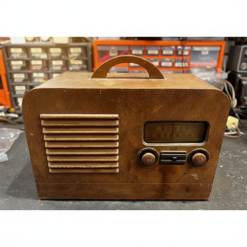
The Belmont General Motors 513
The Portable That Did Everything
AC, DC, or battery — the Belmont 513 came ready for whatever the road threw at it
Some radios know exactly what they are. Console sets sit in the parlour. Table radios sit on the kitchen counter. Automobile sets bolt under the dash. The Belmont 513, however, refused to be categorised. Built in 1940/41 by Belmont Radio Corporation of Chicago, it's a portable set in the truest sense — a self-contained, go-anywhere receiver capable of running on AC mains or internal batteries, depending on the whim of the user and the availability of an outlet.
In a wooden case measuring a practical 13¾ × 9 × 6 inches, the 513 is built around a five-tube superheterodyne circuit — four signal tubes plus a ballast — with a built-in loop antenna and a permanent magnet dynamic speaker. It covers the broadcast band only, which was perfectly sensible in 1941: the AM broadcast band was where the action was, and nobody needed shortwave to hear the morning farm prices.
The tube complement is the period-correct octal portable lineup: a 1A7G pentagrid converter handles the front end and mixing, a 1N5G does IF amplification, a 1H5G covers detection and AVC, and a 1A5G provides the audio output. The rectifier is a 35Z5G, and a 5459 ballast regulates the series heater string. All octal glass types — the Loktal tubes hadn't quite taken over the portable market yet in 1940, and these G-suffix octals were the established reliable choice for low-voltage portable work.
The IF strip is aligned to 465 kHz — slightly above the 455 kHz standard you'll find in most American sets of the era, and worth noting carefully before you go anywhere near an alignment generator. Using the wrong IF frequency during alignment is a fast route to a radio that works technically but sounds like it's tuning through cotton wool.
This particular example came to us via a customer whose father owned it. That changes things. Not the repair process — the soldering iron doesn't care about provenance — but the weight of the job. A radio with a face and a history sitting behind it isn't just a chassis on the bench. It's the reason we do this work.
Sets like this one have a special place in our shop. They're not the rarest, not the most technically complex, not the most valuable by any collector's price guide. But they're the ones that somebody's dad turned on every morning. That somebody grew up hearing. That sat in a specific corner of a specific room in a specific house that no longer exists in quite the same way it used to. You can't put a number on that, and we don't try to. We just make sure it works again.
The wooden cabinet had the honest patina of something that had actually been carried places and lived in a home — which is, after all, exactly what it was designed for. Electrically, the story was considerably less charming.
Power: AC / DC / Battery — 115V AC/DC or 90V battery (B+) + 6V battery (heaters).
Tubes: 1A7G (converter) · 1N5G (IF) · 1H5G (detector/AVC) · 1A5G (output) · 35Z5G (rectifier) · 5459 (ballast).
Circuit: Superheterodyne. IF: 465 kHz. 6 AM tuned circuits. Band: Broadcast (MW) only.
Built-in loop antenna. PM dynamic speaker.
Schematic reference: Beitman Radio Diagrams Vol. 3, 1940. Riders 11/5.

The Knob Problem
Eight decades of dis-similar materials, fused together by time and spite
It was time to disassemble the set. This means removing the knobs — which were tight. As in, "I am now questioning my life choices and the structural integrity of my fingers" tight. There were no set-screws to be backed out, but decades of corrosion and thermal cycling had effectively welded the knobs onto the metal shafts.
Here's the thing about vintage radio knobs: they are irreplaceable. You cannot go to a store and buy a correct-pattern knob for a 1941 Belmont. So brute force is absolutely off the table.

2. Dental floss: Same technique, slightly less leverage. Good for fragile or small knobs.
3. Rubber jar opener: Place over the knob and rotate while lifting. Works when the knob is also rotationally stuck. Only rotate if shaft is non splined.
4. Heat (careful): A hair dryer — not a heat gun — on the knob for 30 seconds can expand the bakelite slightly. Combine with the string method immediately after. Never direct flame. Bakelite does not forgive.
5. Purpose-made knob pullers: Automotive trim tools or specialty radio restoration suppliers. Invaluable for the truly seized ones.
What NOT to do: screwdrivers levered against the cabinet, pliers on the knob body, or anything involving the word "yank." You will regret it.
Do Not Plug This In
The power cord was a fire hazard wearing a power cord costume
Before we even open the service data, we look at the power cord. Because this one had decided — over the course of eight-plus decades — that insulation was more of a suggestion than a requirement. The cloth-and-rubber jacket was cracked extensively. Not "a few hairlines, probably fine" cracked. We're talking full-length, deep fissures exposing bare copper conductor in multiple places along the run. The kind of cord that, if you plugged it in, would briefly make a very loud noise and then possibly start an insurance claim.
The 513 is an AC/DC set — no power transformer. This is not a set you leave connected to an unmonitored outlet with a questionable cord. This set was not going near a wall outlet in its current state. Full stop.
New cord: 18AWG polarised with an inline line filter. On an AC/DC set, the filter matters — these chassis are also notorious for injecting interference back into the mains. The chassis bypass capacitors (the ones that originally bridged line-to-chassis) were replaced with Y-rated safety capacitors. Standard film caps are not rated for line-to-chassis duty. Y-rated caps fail open, not short. That distinction matters a great deal.

▸ The original cord. Extensively cracked, conductor exposed in multiple locations.
Replacement cord: new 18AWG polarised plug with an inline line filter. On an AC/DC set, the filter matters — these chassis are also notorious for injecting hash back into the mains.
The Ballast & The Bad Tube
Two silent killers and a power supply that was deader than disco
New cord installed, multi-section filter capacitors replaced, safety caps in place. Before applying power, both the battery/AC switch and the main power switch were tested for continuity. Both passed. That's the free win of the day.
Every tube heater was tested out-of-circuit with an ohmmeter. The check identified one bad tube: the 35W4 rectifier — open heater. Replaced from stock. Set connected to the variac, voltage brought up slowly. Current draw: essentially zero. Not even the dial lamp flickered.
The culprit was the ballast resistor — measured open circuit. (See image below — white background added for ease of viewing the filament break.) AA5 radios use a series heater string across the AC line. The tube heaters add up to around 105–118V; the ballast drops the remaining voltage and limits cold-start inrush current to protect the filaments. The original ballast tube — a positive-temperature-coefficient resistive device in a tube envelope — was unobtainable in any reliable condition. We replace them with power resistors.

▸ The open ballast resistor — filament break visible against the white background.
Calculate resistance: R = V_drop / I_heater.
Calculate wattage: W = V_drop × I_heater — then double it for reliability.
In this set: a 25W 560Ω resistor for the primary drop, with a 25W 2.5kΩ series resistor to trim heater current precisely. Both chassis-mounted for conductive heat dispersal — the metal chassis acts as a heatsink.
Alternative approaches:
— Diode dropper: silicon diode in series drops ~0.7V, adds half-wave rectification. Simple but changes waveform.
— Capacitive dropper: drops voltage reactively with minimal heat. Frequency-dependent, adds complexity.
— NTC thermistor: modern equivalent of the original ballast — high resistance when cold, lower when hot. Excellent solution when the right value is available.
With the new ballast resistors in place: life. Tube heaters glow, dial lamp illuminates, current draw stable. The heart of the set is beating. The ballast had been silently open for who knows how long — possibly decades. We always use an isolation transformer and our in-house developed dim-bulb-tester when servicing these AC units.

The Silent Treatment
Heaters glow, dial lamp shines — and not a single note of audio
Power supply sorted. Tubes lit. Dial illuminated. We tune to a strong local station. Nothing. Silence. The set produces absolutely no audio whatsoever — like a very expensive night light.
Rather than chase the audio fault on an un-recapped chassis, we did a proper restoration first. All wax and paper capacitors were replaced with modern film types. Whenever replacing higher voltage electrolyte capacitors, be sure to discharge them appropriately. Do not use the screwdriver method! We utilize one of our high-voltage capacitor discharge tools when servicing radios in the shop.

Every resistor was measured against its marked value: almost universal drift greater than 20%, many considerably worse. This is what carbon composition resistors do after seventy-plus years — they drift high, without exception and without apology. Every drifted resistor was replaced.


▸ Inside the chassis — the original wax caps and drifted resistors were replaced throughout.
Resistors: nearly all drifted >20%, many >50%. Full replacement with metal film resistors throughout.
Mica capacitors: measured, found within spec. Left in place. Micas don't lie.
Recap complete. Power on. Still no audio. Signal tracing time. Signal injected at the antenna terminal — traced through the IF strip, detected correctly at the 1H5GT, present at the volume control, and arriving strong and clean at the grid of the 1A5GT audio output tube. Move the probe to the plate of the 1A5GT: nothing. Plate voltage: zero volts. The primary winding of the audio output transformer was open — completely dead, blocking both the B+ supply path and the audio signal simultaneously.

Signal at 1A5GT plate: absent.
B+ voltage at 1A5GT plate: 0V.
Primary winding continuity: OPEN.
Conclusion: audio output transformer primary failure — cause of all audio symptoms.
It Sings Again
A universal transformer, a bottle of Howard's, and a very satisfying afternoon
We keep a stock of universal audio output transformers for exactly this situation. The original transformer's impedance specs were pulled from the service data, a suitable universal unit was selected from the parts shelf, and installed in the output stage.


Power on. Volume up. Tune to a strong signal.
Music.
Actual, genuine, warm, valve-amplified AM radio audio, pouring out of a speaker that hadn't made a sound in what was almost certainly decades. There's a moment in this job — every single time — where a completely silent set comes to life, and it never gets old.
All tubes were then pulled and tested. Every single one came up strong. Where it sat for decades, apparently, was a fine place to store vacuum tubes.
The wood cabinet was cleaned of several decades of dust and insect remains, and inspected. Blemishes on the top surface were treated with Howard's Restor-A-Finish, applied with a soft cloth in the direction of any grain markings. The results were excellent — they largely disappeared, and the cabinet came up looking considerably better with worn patina look that suits the period character of the set.

Audio: present, clear, and properly balanced across the dial.
All tubes: tested strong. No further replacements required.
Cabinet: water stain treated with Howard's Restor-A-Finish — excellent result.
Verdict: complete and operational. The GM 985651 / Belmont BRC-513 is back in service.
In summary: dangerous power cord, seized knobs, failed rectifier tube, open ballast resistor, failed capacitors, universally drifted resistors, and a dead audio output transformer. By any reasonable measure, a thorough mess. And yet — complete, original, structurally sound, cabinet cleaned up beautifully. A great base to start with. The bones were good. Everything else is just parts and labour.
This one goes back to the family it came from. That's the part of this job that doesn't get old — handing a restored radio back to someone and knowing that the thing their father switched on every morning is going to keep working. That it'll be around for another generation to wonder about, or ignore, or rediscover in an attic someday. These are the sets that have a permanent home in our shop's memory, even after they leave the bench. We're glad this one came to us.
Another one back from the dead — and back where it belongs.